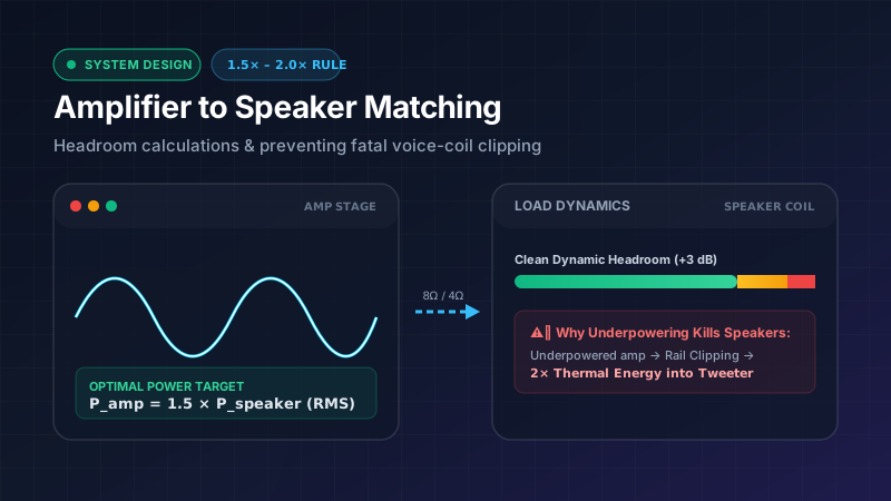
A persistent myth in consumer audio and home theater forums suggests that connecting a high-powered amplifier to a lower-rated loudspeaker will instantly blow the drivers. Beginners often assume that if a speaker is rated for 100 Watts Continuous RMS, pairing it with a 200 Watts RMS amplifier is a guaranteed recipe for catastrophic voice coil destruction.
In reality, professional sound engineers and acoustic technicians know the exact opposite is true:
More loudspeakers and studio monitors are permanently destroyed by underpowered amplifiers driven into hard clipping than by moderately oversized, clean amplifiers with adequate dynamic headroom.
In this comprehensive technical guide, we examine the physics of amplifier clipping, prove why sinusoidal distortion creates fatal high-frequency thermal stress on tweeters, derive the 1.5× to 2.0× continuous RMS headroom rule, and provide real-world impedance matching tables for home audio, car audio, and live sound installations.
1. The Dangerous Counter-Intuition: Why Underpowering Destroys Speakers
To understand why an underpowered amplifier is hazardous to speaker drivers, we must look at what happens inside an amplifier circuit when its volume or input gain is pushed beyond its design limits.
An audio amplifier is an active electronic device that magnifies an incoming audio voltage signal. The maximum peak-to-peak output voltage an amplifier can produce is strictly limited by the direct current (DC) voltage rails of its internal power supply (+V_cc and -V_ee).
Clean Sine Wave (Linear Region):
       +V_peak ───╭───╮───
                  │   │
      0V ─────────┼───┼───
                  │   │
       -V_peak ───╯   ╰───

Hard Clipped Wave (Square Wave Distortion):
       +V_rail ───█████───  <- Peak is flat-topped (High DC & Harmonics)
                  │   │
      0V ─────────┼───┼───
                  │   │
       -V_rail ───█████───  <- Crest factor drops to 1.0; 2x heating power
The Physics of Hard Clipping
When a user drives a 50W amplifier to reproduce a loud transient peak that requires 100W, the output transistors attempt to swing the voltage higher than the power supply rails can support. The amplifier runs out of voltage headroom and shears off the tops and bottoms of the sine wave, flattening them against the supply rails.
This severe non-linear distortion—known as hard clipping—triggers three destructive phenomena:
- Crest Factor Collapse: A pure unclipped sine wave has a voltage crest factor of 1.414 (√2), meaning its continuous heating power is exactly half its peak instantaneous power (P_RMS = 0.5 × P_peak). When hard clipping flattens the wave into an approximate square wave, the crest factor drops to 1.0. The continuous average electrical power delivered to the speaker instantly doubles for the exact same peak voltage!
- Harmonic Energy Shift to the Tweeter: In normal music, the energy distribution across frequencies follows a natural 1/f spectral roll-off (pink noise distribution). Low-frequency woofers handle 70% to 80% of the acoustic energy, while delicate high-frequency tweeters handle only 5% to 15%. When a low-frequency wave clips, Fourier transform analysis proves that the flat tops generate an immense cascade of high-amplitude, high-frequency odd harmonics (3rd, 5th, 7th, 9th, etc.). This massive high-frequency energy bypasses the woofer and is routed directly by the crossover network into the fragile, ultra-thin voice coil of the tweeter.
- Voice Coil Thermal Meltdown: While the woofer’s large magnet assembly and heavy aluminum former can dissipate modest thermal overloads, a 1-inch silk or titanium dome tweeter voice coil can typically withstand only 10 to 25 Watts of continuous thermal dissipation. The flood of ultrasonic harmonic energy from a clipped 50W amplifier heats the tweeter coil past 200°C in seconds, boiling the voice coil adhesive, melting the insulation lacquer, and causing an open-circuit short.
2. Understanding Speaker Power Ratings: RMS, Program, and Peak
Loudspeaker specification sheets frequently cite multiple conflicting power numbers. To properly size an amplifier, you must understand what each rating physically represents:
Continuous Average Power (True RMS)
The continuous RMS rating (often denoted as Continuous Power or AES Power) is the maximum steady-state electrical power a speaker can absorb continuously over a multi-hour test without thermal failure. This is determined according to international testing standards such as IEC 60268-5 using bandwidth-limited shaped pink noise over a 2-hour or 100-hour stress test.
Program Power (Music Power)
Because real-world music and speech are dynamic rather than continuous test tones, speakers can safely absorb higher transient peaks if accompanied by brief cooling intervals. Program Power is universally defined as exactly 2.0× the Continuous RMS rating:
Program Power = 2.0 × Continuous RMS Power
Peak Instantaneous Power
Peak power represents the absolute maximum burst energy a loudspeaker voice coil and suspension (spider and surround) can tolerate for a few milliseconds without mechanical bottoming or thermal destruction. Peak power is defined as:
Peak Power = 2.0 × Program Power = 4.0 × Continuous RMS Power
┌─────────────────────────────────────────────────────────────┐
│                 LOUDSPEAKER POWER SPECTRUM                  │
├───────────────────────────────┬──────────────┬──────────────┤
│ 100W Continuous RMS (IEC)     │ 200W Program │ 400W Peak    │
│ (Continuous Thermal Baseline) │ (Music 2×)   │ (Burst 4×)   │
└───────────────────────────────┴──────────────┴──────────────┘
3. The Mathematical Derivation of the 1.5× to 2.0× Headroom Rule
Why do acoustic engineers recommend an amplifier rated between 1.5× and 2.0× the speaker’s continuous RMS rating?
Music is composed of dynamic transients: snare drum hits, kick drums, acoustic guitar plucks, and orchestral crescendos. The ratio between the peak transient level and the average continuous level in high-fidelity recordings is called the Dynamic Crest Factor, which typically ranges from 10 dB to 20 dB (a peak-to-average power ratio of 10:1 to 100:1).
If an amplifier is sized to match the speaker’s continuous rating exactly (1.0×):
- Running the system at an average level of only 10 Watts RMS will mean that dynamic 100 Watt peaks hit the absolute ceiling of the amplifier rails.
- If the user turns the volume up slightly to achieve 25 Watts average listening level, any 10 dB musical transient demanding 250W will clip violently, spraying high-frequency distortion into the tweeters.
The Headroom Equation
By choosing an amplifier rated at 1.5× to 2.0× the speaker’s continuous RMS rating, you establish +1.76 dB to +3.01 dB of clean dynamic headroom:
Δ Headroom (dB) = 10 × log10(P_Amp / P_Speaker_RMS)
- For
P_Amp = 1.5 × P_Speaker_RMS→10 × log10(1.5) = +1.76 dB - For
P_Amp = 2.0 × P_Speaker_RMS→10 × log10(2.0) = +3.01 dB
With 3 dB of headroom, the amplifier can cleanly reproduce explosive transient peaks up to the speaker’s full Program Power rating without clipping its output voltage stage, delivering pristine acoustic fidelity, zero harsh distortion, and maximum speaker protection.
4. The Impedance Factor: Matching Load Curves (Ω)
An amplifier’s output wattage is never a fixed single number; it is fundamentally governed by Ohm’s Law and the load impedance connected to its output terminals:
P = V² / R
Where:
Pis the continuous power in Watts.Vis the RMS output voltage delivered by the output stage.Ris the speaker’s nominal load impedance in Ohms (Ω).
Because load impedance sits in the denominator, halving the speaker impedance theoretically doubles the power demand placed on the amplifier’s power supply and output transistors (assuming the power supply is robust enough to deliver the required current).
Typical Solid-State Amplifier Output vs. Impedance:
┌───────────────┬──────────────────────┬──────────────────────┐
│ Load (Ohms)   │ Continuous RMS Power │ RMS Output Voltage   │
├───────────────┼──────────────────────┼──────────────────────┤
│ 8 Ω Nominal   │ 100 Watts RMS        │ 28.28 V RMS          │
│ 4 Ω Nominal   │ 180 Watts RMS        │ 26.83 V RMS          │
│ 2 Ω Nominal   │ 300 Watts RMS        │ 24.49 V RMS          │
└───────────────┴──────────────────────┴──────────────────────┘
Engineering Caution: Always match the amplifier’s rated output power at the exact nominal impedance of your speaker. An amplifier rated at 200W into 4 Ω will only produce approximately 100W to 120W when connected to an 8 Ω speaker!
5. Comprehensive Amplifier Sizing Matrix
Use this engineering lookup table to identify the optimal amplifier continuous RMS power range across common speaker power ratings and load impedances:
| Speaker Rating (Continuous RMS) | Speaker Nominal Impedance | Recommended Amp RMS (1.5× – 2.0×) | Safe Maximum Program Limit | Minimum Cable Wire Gauge (10m / 30ft) |
|---|---|---|---|---|
| 25 Watts RMS | 8 Ω | 38W – 50W RMS | 50 Watts | 18 AWG |
| 50 Watts RMS | 8 Ω | 75W – 100W RMS | 100 Watts | 16 AWG |
| 50 Watts RMS | 4 Ω | 75W – 100W RMS | 100 Watts | 16 AWG |
| 100 Watts RMS | 8 Ω | 150W – 200W RMS | 200 Watts | 14 AWG |
| 100 Watts RMS | 4 Ω | 150W – 200W RMS | 200 Watts | 14 AWG |
| 150 Watts RMS | 8 Ω | 225W – 300W RMS | 300 Watts | 14 AWG |
| 250 Watts RMS | 8 Ω | 375W – 500W RMS | 500 Watts | 12 AWG |
| 250 Watts RMS | 4 Ω | 375W – 500W RMS | 500 Watts | 12 AWG |
| 500 Watts RMS | 8 Ω | 750W – 1,000W RMS | 1,000 Watts | 12 AWG |
| 500 Watts RMS | 4 Ω | 750W – 1,000W RMS | 1,000 Watts | 10 AWG |
| 1,000 Watts RMS | 4 Ω | 1,500W – 2,000W RMS | 2,000 Watts | 10 AWG |
| 1,000 Watts RMS | 2 Ω | 1,500W – 2,000W RMS | 2,000 Watts | 8 AWG |
6. Practical Setup Guide by Application
A. Home Hi-Fi & Studio Monitoring
- Target Ratio: 1.5× Continuous RMS.
- Goal: Maintain total harmonic distortion (THD+N) below 0.01% during standard acoustic listening levels.
- Safety Tip: Ensure the amplifier’s damping factor is ≥ 100 at 8 Ω to maintain tight low-frequency transient control over the woofer cone.
B. Car Audio Systems & Monoblock Subwoofers
- Target Ratio: 1.25× to 1.5× Continuous RMS.
- Goal: High current delivery into low-impedance loads (1 Ω or 2 Ω).
- Safety Tip: Car electrical systems operate on nominal 12V to 14.4V DC. Heavy bass transients can cause input voltage sag down to 11V, inducing premature amplifier clipping. Always verify battery and alternator capacity before increasing amplifier gain. Use our Car Audio RMS Calculator to calculate electrical current draw.
C. Live Sound, Touring PA & Concert Installations
- Target Ratio: 2.0× Continuous RMS.
- Goal: High Sound Pressure Level (SPL) output across large open spaces with zero audible distortion.
- Safety Tip: Always employ a Digital Signal Processor (DSP) with a calibrated brickwall RMS and Peak limiter. Set the RMS limiter to the speaker’s thermal threshold and the peak limiter to prevent mechanical over-excursion.
7. How to Set Amplifier Gains with a Digital Multimeter (DMM)
To ensure your matched amplifier never outputs a clipped voltage signal, calibrate your amplifier’s input sensitivity (gain) using an AC True-RMS Digital Multimeter:
- Disconnect Speakers: Unplug all speaker wire terminals from the amplifier output channels.
- Calculate Target Voltage: Use the Ohm’s Law voltage formula:
V_Target_RMS = √(P_Target × R_Load)Example: For 150W RMS into an 8 Ω load: V = √(150 × 8) = √1200 ≈ 34.64 V RMS. - Play Test Tone: Play a 0 dB uncompressed sinusoidal test tone through your source unit:
- Use 50 Hz for subwoofers.
- Use 1 kHz for full-range speakers.
- Set Source Volume: Turn the head unit or mixer master volume to 75% to 80% to avoid pre-amp clipping.
- Adjust Gain Dial: Connect the multimeter test leads to the amplifier speaker terminals (set to AC Volts). Slowly turn the gain dial until the multimeter reads exactly your target voltage (34.64 V).
8. Frequently Asked Questions (FAQ)
Can an oversized amplifier damage my speakers if I turn the volume all the way up?
Yes. An amplifier with 2.0× headroom provides clean dynamic power for normal music transients. However, if you intentionally push the system to sustained maximum volume with heavily compressed audio (such as unmastered synth tones or feedback), the continuous power will exceed the speaker’s continuous thermal limits, causing thermal failure. Headroom is designed for clean transient peaks, not sustained overload.
Is a 4-Ohm amplifier safe to use with 8-Ohm speakers?
Yes, absolutely. Connecting an 8 Ω speaker to an amplifier rated for 4 Ω is completely safe. The higher impedance simply presents an easier load for the amplifier, causing it to draw less current and run cooler. The amplifier will produce approximately 50% to 60% of its 4 Ω power rating.
Is an 8-Ohm amplifier safe to use with 4-Ohm speakers?
Only if the amplifier specifically states 4 Ω stability in its technical manual. Connecting a 4 Ω speaker to an amplifier designed solely for 8 Ω loads will cause the output stage to draw twice as much current, potentially triggering thermal protection shutdown or blowing output fuses.
What is the difference between Peak Power and Program Power?
Program Power (Music Power) is 2× continuous RMS power and represents what a speaker can handle with dynamic music. Peak Power is 4× continuous RMS power (2× Program Power) and represents the absolute millisecond burst limit before mechanical or electrical breakdown.
Summary & Next Steps
Matching your amplifier to your loudspeakers using the 1.5× to 2.0× headroom rule is the single most effective way to eliminate harsh distortion, maximize sound clarity, and protect your drivers from fatal clipping damage.
Use our interactive engineering calculators to size your audio components accurately:
- Main RMS to Watts Calculator — Instant multi-mode continuous power calculations.
- Speaker RMS to Watts Calculator — Load impedance and wattage sizing.
- Amplifier to Speaker Matching Calculator — Live headroom ratio solver.
- RMS vs Peak Watts Calculator — 2× continuous vs instantaneous peak breakdown.