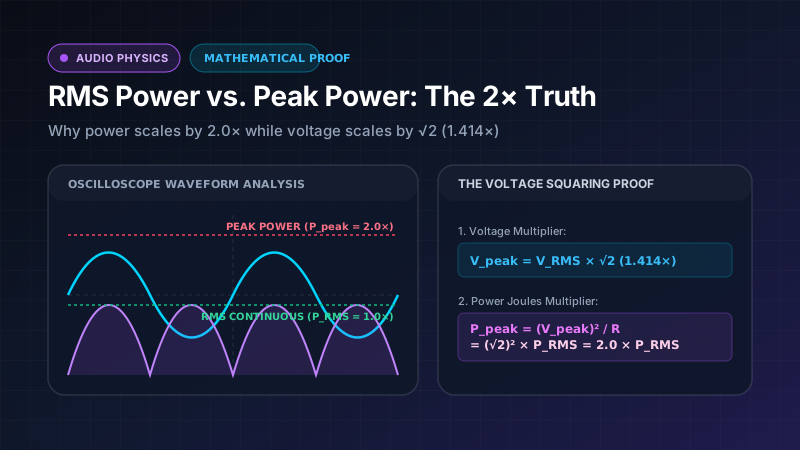
One of the most persistent controversies in electrical engineering forums, amateur car audio discussions, and poorly documented online conversion tools is the exact mathematical relationship between Continuous Average Power (commonly called RMS Power) and Peak Instantaneous Power for a pure sinusoidal waveform.
A surprising number of online articles and forums erroneously state:
“Because peak voltage is √2 ≈ 1.414× RMS voltage, peak power must also be 1.414× RMS power.”
This statement is mathematically, physically, and experimentally false.
For any pure sinusoidal alternating current (AC) voltage driving a linear resistive load, Peak Instantaneous Power is exactly 2.0× Continuous Average Power (RMS Power):
P_Peak = 2.0 × P_RMS
In this comprehensive engineering breakdown, we provide the first-principles calculus proof, explain why squaring the voltage multiplier changes the ratio, explore why the term “RMS Power” is technically an engineering misnomer, and present real-world bench oscilloscope data.
1. The Root of the Misconception: Voltage vs. Power Ratios
The primary reason enthusiasts confuse the power ratio is a failure to distinguish between linear field quantities (Voltage and Current) and quadratic energy quantities (Power and Heat).
The Voltage Crest Factor (√2)
For a pure sinusoidal AC waveform, the Peak Voltage (V_Peak) is the maximum amplitude reached at the very apex of the sine wave cycle (90° and 270°). The Root Mean Square Voltage (V_RMS) represents the equivalent DC voltage that would dissipate the exact same thermal heating energy across a resistive load.
The mathematical relationship between peak voltage and RMS voltage for a sine wave is:
V_Peak = √2 × V_RMS ≈ 1.4142 × V_RMS
V_RMS = V_Peak / √2 ≈ 0.7071 × V_Peak
The Joule Heating Law (The Squaring Effect)
Electrical power dissipated across a resistive load R is fundamentally governed by Joule’s First Law and Ohm’s Law:
P = V × I = V² / R = I² × R
Notice the exponent: Power is proportional to the square of voltage (V²).
When you substitute the peak voltage (V_Peak = √2 × V_RMS) into the power formula:
P_Peak = (V_Peak)² / R = (√2 × V_RMS)² / R = (2 × V_RMS²) / R = 2.0 × P_RMS
Because (√2)² = 2, the voltage multiplier of 1.4142 is squared, resulting in an exact 2.0× power ratio.
Sine Wave Voltage & Power Visual Comparison:
Voltage Waveform v(t):
    +V_peak ───╭───╮───  (V_peak = 1.414 * V_RMS)
               │   │
   0 Volts ────┼───┼───
               │   │
    -V_peak ───╯   ╰───

Instantaneous Power Waveform p(t) = v(t)² / R:
    P_peak  ───╭─╮─╭─╮─  (P_peak = 2.0 * P_average)
               │ │ │ │   Power is always positive! Pulsates at 2x frequency.
   P_avg    ───┼─┼─┼─┼─  (P_average = Continuous RMS equivalent)
   0 Watts  ───┴─┴─┴─┴─
2. First-Principles Calculus Proof: Integrating Continuous Average Power
To provide undeniable proof, let us derive continuous power from basic calculus definitions.
Let a sinusoidal voltage across a load resistor R be defined as:
v(t) = V_Peak × sin(ωt)
The instantaneous power p(t) delivered to the load at any instant in time t is:
p(t) = v(t)² / R = [V_Peak² × sin²(ωt)] / R
Calculating the Continuous Average Power
The continuous average power delivered over one complete cycle period T is obtained by integrating p(t) over time:
P_avg = (1 / T) × ∫ [p(t)] dt from 0 to T
Using the standard trigonometric identity sin²(θ) = [1 - cos(2θ)] / 2:
P_avg = [V_Peak² / (2 × R × T)] × ∫ [1 - cos(2ωt)] dt from 0 to T
Evaluating the integral over the full period:
∫ 1 dt = T∫ cos(2ωt) dt = 0(the integral of a full-period sinusoid is zero)
Substituting these values back into the equation:
P_avg = [V_Peak² / (2 × R × T)] × T = V_Peak² / (2 × R)
Peak Instantaneous Power Calculation
The peak instantaneous power occurs at the crest of the sinusoid when sin(ωt) = ±1:
P_Peak = [V_Peak² × (±1)²] / R = V_Peak² / R
The Exact Mathematical Ratio
Taking the ratio of Peak Power to Average Continuous Power:
P_Peak / P_avg = (V_Peak² / R) / [V_Peak² / (2 × R)] = 2.0
This proves conclusively that for any sinusoidal AC electrical signal, Peak Power is exactly twice the Continuous Average Power.
3. Why “RMS Power” is Technically an Engineering Misnomer
In consumer electronics and audio marketing, the term “RMS Power” (or Watts RMS) is universally used to describe continuous output capability. However, professional electrical engineers and standards bodies like the IEEE and Audio Engineering Society (AES) frequently point out that the term is technically a misnomer.
The Mathematical Reason
- Root Mean Square (RMS) is a statistical mathematical operation defined as taking the square root of the mean of squared values over time.
- When applied to voltage
v(t), the RMS calculation yieldsV_RMS = V_Peak / √2, which correctly represents the equivalent DC voltage for heating. - However, if you apply the RMS formula directly to the instantaneous power function
p(t) = v(t)² / R, you are computing the root-mean-square of squared quantities (v^4). The mathematical result has no physical meaning in thermodynamics and does not equal the thermal work done on a resistor!
What the audio industry calls “RMS Watts” is actually:
“Continuous Average Power calculated from True-RMS Voltage and True-RMS Current.”
Continuous Average Power = (V_RMS)² / R = I_RMS² × R = V_RMS × I_RMS × Power Factor
While we continue to use the term “RMS Watts” for consumer familiarity, keep in mind that scientifically, it represents Continuous Average Thermal Dissipation.
4. Waveform Comparison: Crest Factors & Power Scaling Ratios
The 2.0× power scaling factor applies specifically to pure sine waves. Different waveform shapes produce different voltage crest factors and peak-to-average power ratios (PAPR):
| Waveform Type | Voltage Crest Factor (V_Peak / V_RMS) | RMS Voltage (from V_Peak) | Peak-to-Average Power Ratio (P_Peak / P_Avg) | Primary Real-World Application |
|---|---|---|---|---|
| Pure Sine Wave | 1.414 (√2) | 0.7071 × V_Peak | 2.00× (+3.01 dB) | Standard Bench Testing, AC Mains Power |
| Square Wave | 1.000 | 1.0000 × V_Peak | 1.00× (0.00 dB) | Digital Clock Signals, Severely Clipped Amps |
| Triangle Wave | 1.732 (√3) | 0.5774 × V_Peak | 3.00× (+4.77 dB) | Synthesizers, Signal Generators |
| Sawtooth Wave | 1.732 (√3) | 0.5774 × V_Peak | 3.00× (+4.77 dB) | CRT Deflection, Analog Synthesis |
| Pink Noise (IEC 60268) | 2.000 | 0.5000 × V_Peak | 4.00× (+6.02 dB) | Loudspeaker Stress & Thermal Testing |
| Dynamic Music (Classical) | 3.16 to 10.0 (10–20 dB) | 0.1000 to 0.3162 × V_Peak | 10.0× to 100.0× | High-Resolution Acoustic Recordings |
5. Real-World Engineering Bench Test Example
Let us examine a laboratory bench test of an audio power amplifier driving an 8 Ω non-inductive dummy load:
┌─────────────────────────────────────────────────────────────┐
│               LABORATORY BENCH TEST DATA                    │
├───────────────────────────────┬─────────────────────────────┤
│ Oscilloscope Channel 1        │ 40.00 Volts Peak (80.0 Vpp) │
│ Fluke 87V True-RMS Multimeter │ 28.28 Volts RMS             │
│ Load Resistor (Dummy Load)    │ 8.00 Ohms Non-Inductive     │
└───────────────────────────────┴─────────────────────────────┘
Step-by-Step Calculation:
-
Continuous Average Power (RMS Power):
P_RMS = (28.28 V)² / 8 Ω = 800.0 V² / 8 Ω = 100.0 Watts RMS -
Continuous RMS Current Draw:
I_RMS = 28.28 V / 8 Ω = 3.535 Amperes RMS -
Peak Instantaneous Voltage:
V_Peak = 28.28 V × 1.4142 = 40.00 Volts Peak -
Peak Instantaneous Current:
I_Peak = 40.00 V / 8 Ω = 5.00 Amperes Peak -
Peak Instantaneous Power:
P_Peak = 40.00 V × 5.00 A = 200.0 Watts Peak -
Validation:
P_Peak / P_RMS = 200.0 W / 100.0 W = 2.00
As shown by the physical data, the instantaneous power at the peak of the waveform is exactly 200 Watts, confirming the 2× ratio.
6. Why Amplifiers Cannot Sustain Peak Power Continuously
If an amplifier can produce 200W peak power, why is it only sold as a “100W amplifier”?
Continuous power rating is dictated by thermal equilibrium and power supply capacity:
- Heatsink Thermal Time Constants: Silicon output transistors generate waste heat. While the transistor junction can briefly handle 200W instantaneous power for a fraction of a millisecond, sustaining that level continuously would raise junction temperatures above 150°C, triggering catastrophic thermal runaway.
- Transformer & Power Supply Sag: The power transformer, bridge rectifier, and filter capacitors are sized to deliver continuous current for the RMS rating. Under sustained heavy loads, the capacitor reservoir depletes, and internal resistance causes DC rail voltage to sag from +50V down to +38V, lowering maximum peak output.
- Power Factor & Reactive Impedance: Real loudspeakers have complex reactive impedance with phase angles up to ±60°. Voltage and current waveforms fall out of phase, requiring the amplifier to dissipate excess energy internally during the cycle.
7. Frequently Asked Questions (FAQ)
What is Peak-to-Peak Voltage (V_p-p) and how does it relate to Power?
Peak-to-Peak voltage is the total vertical voltage difference between the positive crest and the negative trough:
V_p-p = 2 × V_Peak = 2√2 × V_RMS ≈ 2.8284 × V_RMS
To calculate RMS power from V_p-p:
P_RMS = (V_p-p / 2√2)² / R = V_p-p² / (8 × R)
Is Peak Power the same as PMPO?
No. Peak Power (2× RMS for a sine wave) is a mathematically sound, physically real measurement of the instantaneous power at the crest of the waveform. PMPO (Peak Music Power Output) is an arbitrary, non-standardized marketing gimmick that exaggerates ratings by 10× to 50×. Read our deep dive: The Truth About PMPO & IEC 60268-5.
Why do some audio companies advertise “Dynamic Power” higher than 2× RMS?
Dynamic power (or IHF Dynamic Headroom) measures an amplifier’s ability to deliver burst power for 20 ms into a load using energy stored in large power supply reservoir capacitors. Premium amplifiers with stiff power supplies can output 1.5 dB to 3 dB of dynamic headroom above their continuous rating.
Summary & Key Takeaways
- Voltage Ratio: Peak Voltage is 1.414× (√2) RMS Voltage.
- Power Ratio: Peak Instantaneous Power is 2.0× Continuous Average Power (RMS Power).
- Physical Reason: Power is proportional to voltage squared (P ∝ V²), and (√2)² = 2.0.
- Industry Convention: “RMS Watts” scientifically represents continuous thermal dissipation capacity.
Explore our interactive engineering tools to run live waveform conversions:
- Main RMS to Watts Calculator — Instant multi-mode solver with live oscilloscope visualization.
- RMS to Peak Watts Calculator — Live 2× scaling and V_p-p analyzer.
- Crest Factor Calculator — Audio dynamic range and PAPR solver.
- RMS Voltage Calculator — Convert between V_RMS, V_Peak, and V_p-p.